Union Intelligent CNC Industrial Park A&B, Hefei, China 231131
News
A Practical Guide for Fiber Laser Cutting EV Motor Laminations
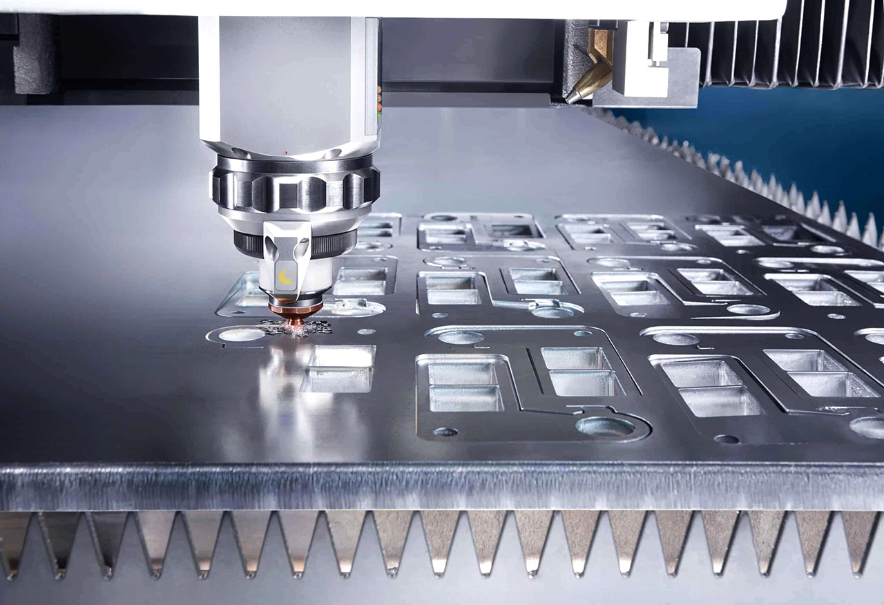
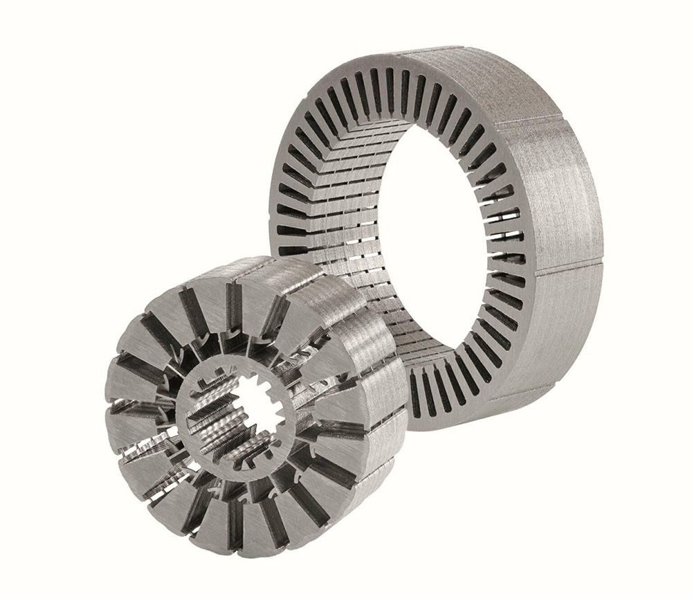
Electric vehicle traction motors use laminated electrical steel to form their stator and rotor cores. Each lamination has a specific outer profile, inner opening, and a series of slots. The dimensions and edge quality of these features affect assembly and motor performance.
Stamping is the established choice for large-scale production, but developing new motor designs often involves frequent changes to lamination geometry. In this situation, a fiber laser cutting machine offers greater flexibility for prototyping, design validation, and small-batch manufacturing.
Choosing the right equipment requires more than looking at laser power. Sheet dimensions, positioning performance, workpiece stability, and the quality of the finished laminations all need to be considered.
Choose Laser Power and Working Area Based on the Material
Non-oriented electrical steel used in motor cores commonly has a thickness of 0.35–0.5 mm. For this range, 1.5–3 kW is a reasonable power range to evaluate when selecting a machine. The actual requirement depends on cutting speed, edge quality, and whether single-layer or multi-layer processing is planned.
A 3000W laser cutting machine provides more processing capacity, but higher power does not automatically mean better results on thin electrical steel. Excessive heat input can increase the risk of thermal distortion and affect the material near the cut edge. Sample cutting is therefore necessary before finalizing the power configuration.
Our production recommendation: 3000W Fiber Laser Cutting Machine
The working area should match the dimensions of the sheets being processed. A 1000 × 1000 mm or 1500 × 1000 mm table may be sufficient for small prototypes. If the material comes in standard sheets measuring 1250 × 2500 mm or 1500 × 3000 mm, a larger working area will be needed.
There is little benefit in choosing an oversized machine if the material and parts are relatively small. The goal is to match the equipment to the actual production requirements.
Evaluate the Machine's Ability to Maintain Accuracy
Motor laminations often contain narrow stator slots and precisely positioned rotor magnet slots. Small deviations can cause problems during assembly, so the machine must maintain consistent positioning across its working area.
For precision prototype work, ±0.03 mm/m positioning accuracy and ±0.02 mm repeatability can serve as initial equipment selection targets. These figures describe machine performance, not the dimensional tolerance of the finished part. Ask the manufacturer how the figures are measured, and verify them through full-travel testing and sample cutting.
The mechanical transmission system is equally important. A suitable CNC fiber laser cutting machine should have a stable frame, properly installed linear guides, and a transmission system designed to minimize backlash.
Servo motors from brands such as Yaskawa, Panasonic, and Inovance are common options. For a gantry-type machine, a dual-drive Y axis with synchronized control helps maintain movement on both sides. Preloaded linear guides from HIWIN, THK, or PMI can also be considered. Guide size should be selected according to the machine's load and structural design; 25–30 mm is only an initial reference.
For rack-driven axes, a precision helical rack and pinion system paired with low-backlash gearboxes is worth considering. Ground racks with a DIN 6 or higher accuracy grade are suitable options. Linear scales can provide direct position feedback and may be useful when tighter positioning requirements apply, provided that the control system, installation, and temperature compensation are properly addressed.
Control Thin-Sheet Movement and Heat During Cutting
Thin electrical steel is relatively easy to deform. Even when the machine has good positioning performance, an unstable sheet can still produce inaccurate parts.
Workpiece fixation should therefore be considered during equipment selection. Vacuum tables may seem suitable for thin sheets, but the numerous slots and openings in motor laminations can cause air leakage and reduce holding force. Depending on the part layout, mechanical fixtures, magnetic assistance, or zoned vacuum systems may be more practical.
The cutting sequence also matters. Concentrating too much heat in one area can cause local distortion. A well-planned path should distribute heat as evenly as possible while maintaining efficient cutting order.
CCD positioning is useful when sheets are pre-cut, manually loaded, or not consistently aligned. It can identify sheet edges or reference marks before processing. For regularly positioned sheets, however, it may not be necessary.
Fume extraction and laser protection are basic equipment requirements rather than optional performance upgrades. A zoned extraction system helps remove fumes close to the cutting area, while a fully enclosed structure with safety interlocks provides better operator protection. An exchange table is mainly worth considering when production volume makes loading and unloading time a significant part of the overall cycle.
Verify Cutting Quality Through Sample Processing
Before purchasing equipment or starting production, test it with the actual electrical steel and part drawings. A practical trial should include the outer contour, inner opening, stator slots, and rotor magnet slots.
Start with a representative 0.35 mm sheet and inspect the results. Pay particular attention to slot width, hole dimensions, edge condition, dross, and sheet flatness.
If dross appears on the cut edge, check the focal position, assist gas pressure, and nozzle condition. If the sheet warps, review the cutting sequence and heat input. Changing laser power alone may not solve either problem.
Use a 2D measuring system to check critical dimensions against the drawings. For high-performance motor applications, dimensional inspection may not be enough. Laser cutting can alter the magnetic properties of electrical steel near the cut edge, so magnetic performance should also be evaluated when it is critical to the motor design.
Click For more technical articles.
A suitable laser cutting machine for electrical steel should therefore be judged by the results it produces on the actual material, not just its advertised specifications. The most useful acceptance test combines positioning measurements, sample cutting, dimensional inspection, and an assessment of edge quality.
The right configuration is ultimately the one that meets the required part quality without unnecessary equipment costs or excessive processing complexity.




Leave a Comment